Along with the application of technology and advances in the field of design and manufacture of transformers, it is possible to manufacture machines with super high voltage and extremely large capacity, but the structure as well as the operating principle of the transformer. there seems to be no change.
TABLE OF CONTENTS
1. What is a transformer?
2. General structure of transformer
a. Steel core
b. Winding wire
c. Case
3. Uses of transformers
4. Working principle of transformer
5. Types of transformers
6. Transformer quotation
1. What is a transformer?
A transformer or transformer is a static electromagnetic device, working on the principle of electromagnetic induction, used to change the system voltage, with a constant frequency.
In transformers, voltage conversion is only possible when the current is alternating or pulsed. Transformers are used in power transmission and distribution systems, in addition, transformers are also used for a number of other requirements such as connecting rectifier circuits, as a power supply for electric furnaces, welding machines, testing machines. … Transformer with two or more windings placed together on a magnetic circuit, the windings can be electrically connected or non-electrically connected, when they are electrically connected, it is called an autotransformer.
2. General structure of transformer
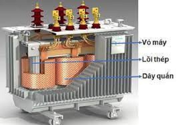
The general structure of all transformers consists of 3 main components: Steel core, windings and case.
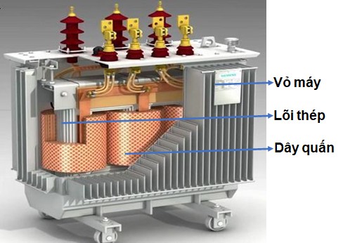
Figure 1. Construction of transformer
a. Steel Core (Magnetic Circuit)
The steel core used to conduct the flux is made of good conductive materials. Paired from electrical engineering steel sheets into a closed loop circuit, the outer thin steel sheets are painted with insulating paint with a thickness of 0.3 – 0.5mm.
Steel core consists of 2 parts including Pillar and Gong. The post is the part to place the winding wire and the gong is the connecting part between the pillars to form a closed magnetic circuit.
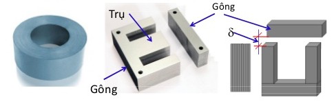
Figure 2. Steel core of transformer
b. Winding wire
The job of the coil is to receive energy in and transfer energy out.
Winding wire is usually made of copper or aluminum wire, round or rectangular cross-section, with insulation on the outside. The winding consists of many turns of wire and is inserted into the steel post. There is insulation between the turns of the wire, between the windings and between the winding and the pressing core. Transformers usually have two or more windings. and the number of turns of the coils is different, depending on the duty of the transformer.
There are two types of windings: primary winding and secondary winding
- The winding that receives energy from the grid is called the primary winding
- The winding that supplies energy to the load is called the secondary winding
The number of turns of the primary and secondary coils is different. The number of turns of the primary winding is greater than the number of turns of the secondary winding, then it is a low voltage transformer (low voltage transformer), otherwise the number of turns of the primary winding is smaller than the number of turns of the secondary winding, it is a transformer. booster (boost transformer).
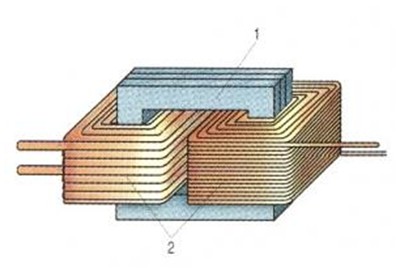
Figure 3. Winding of transformer
In addition, one can also distinguish transformer winding into high voltage winding and low voltage winding.
- A winding with a high voltage is called a high voltage winding
- The winding with the lower voltage is called the low voltage winding
In terms of structure, winding wire is divided into 2 types: concentric winding and alternating winding.
- Concentric winding: whose cross-section is concentric circles. The main types of concentric windings include:
- Cylindrical winding, for both low and high voltage windings (figure 4a).
- Twisted winding, for low-voltage winding with many shorted wires (figure 4b).
- Continuous spiral winding, for high-voltage winding, rectangular conductor cross-section (Figure 4c).
- Alternating winding: The high and low voltage gears alternately alternate along the steel pole (Figure 4d).
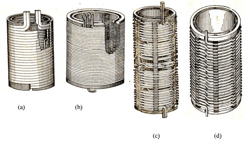
Figure 4. Types of winding transformers
c. Case
Depending on the type of transformer, the transformer housing is made of different materials. They are usually made from plastic, wood, steel, cast iron or thin corrugated iron, which are used to protect the transformer’s elements inside it, including: the lid of the tank and the box.
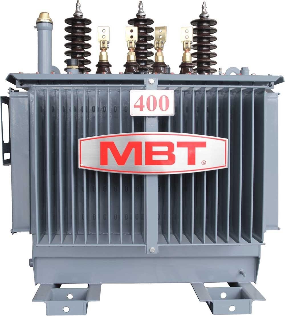
Figure 5. MBT 3-phase transformer steel case
The lid is used to cover the barrel and has important parts on it such as:
- Output (insulator) of high-voltage winding and low-voltage winding.
- Oil expansion tank (auxiliary oil tank) with glass tube to see the oil level
- Insurance tube: made of steel, inclined cylinder, one end connected to the barrel, one end sealed with a glass disc. If the pressure in the tank increases suddenly, the glass disc will break, the oil will escape so that the transformer will not be damaged.
- Small hole for thermometer.
- Steam relays are used to protect transformers.
- The breaker actuator connects the voltage regulator terminals of the high-voltage winding.
3. Uses of transformers
Transformers can be used to increase the voltage from the generator to the transmission line for long distances, and to reduce the voltage at the end of the line to provide a suitable voltage source for the load.
In addition, they are also used in furnaces, welding, measuring or as a power source for electrical and electronic equipment.
Reference articles:
The importance of transformers
4. Working principle of transformer
Transformers operate according to two physical phenomena:
The current flowing through the conductor creates a magnetic field.
– The flux change in the coil creates an induced voltage (electromagnetic induction phenomenon).
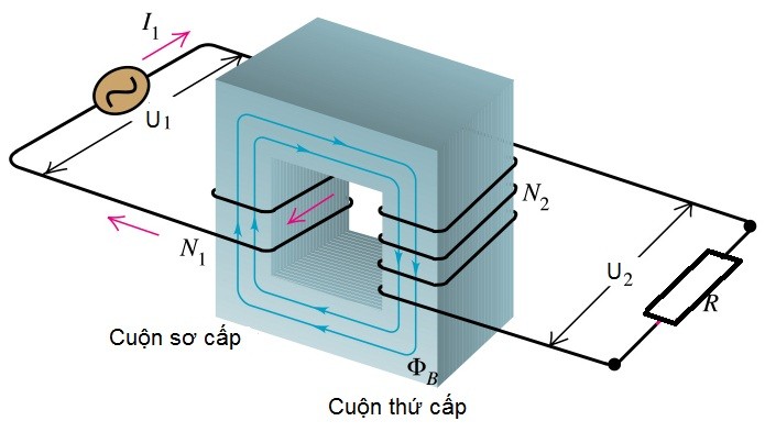
Figure 6. Working principle of transformer
Coil N1 and coil N2 are wound on a closed steel core. Applying an alternating voltage U1 to coil N1, on this coil, current I1 will flow in the conductor, and in the conductor will appear a looping flux for both coils N1 and N2. When coil N2 is connected to the load, coil N2 will appear current I2 with voltage U2. Thus, the energy of the alternating current has been transferred from winding 1 to winding 2.
5. Types of transformers
There are many types of transformers. Some classifications:
- Classification by structure: 1 phase transformer and 3 phase transformer
- Classification by function: step-up transformers and step-down transformers
- Classified by use: experimental transformers, measuring transformers, autotransformers,…
- Sort by specifications
- Classification by way of insulation: dry transformers and oil transformers